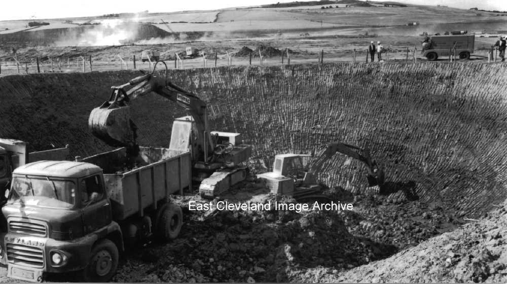
The second bucket fills the lorry.
Image courtesy of Alan Franks.
|
|
||
|
The second bucket fills the lorry. Image courtesy of Alan Franks.
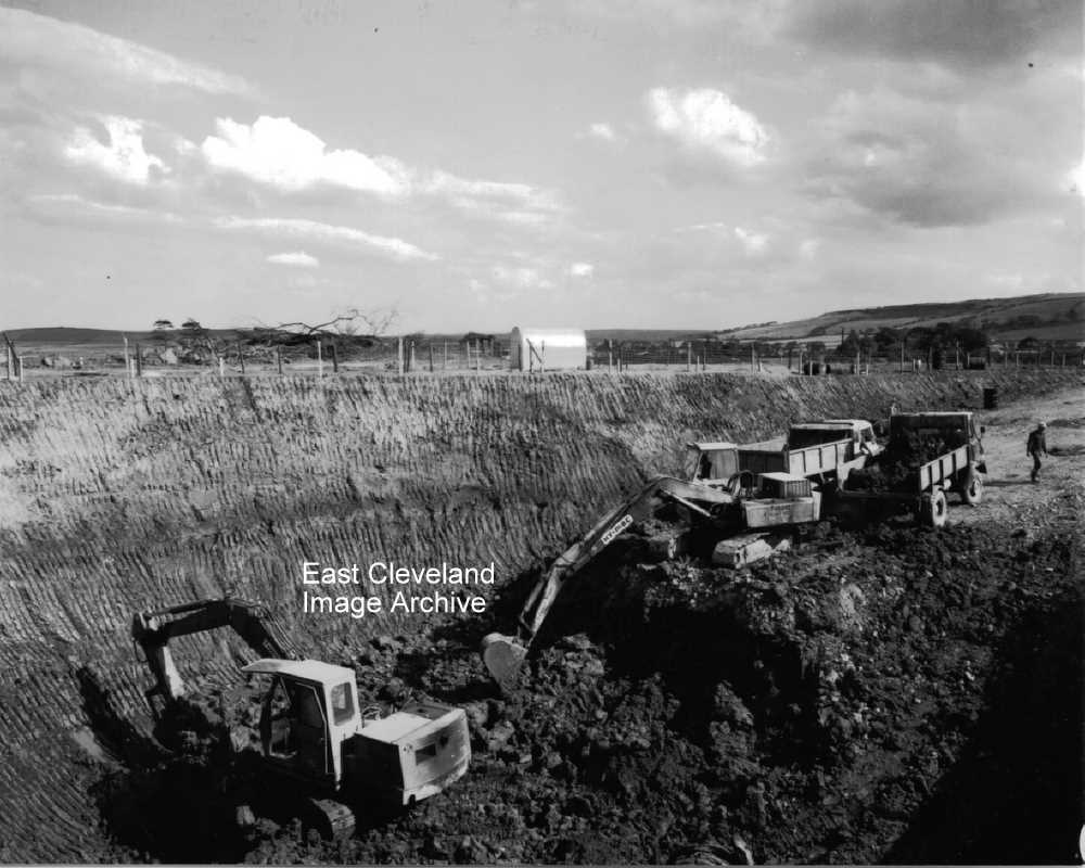
The first bucket digs the hole and puts its load where the second bucket can get it. Image courtesy of Alan Franks.
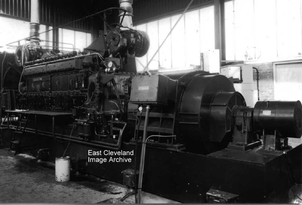
This looks like a motor-generator unit – looks pretty beefy too – please correct us if we’re wrong! Terry Robinson tells us: ”This is the Blackstone Mirlees emergency generator unit, which is situated opposite the surface engineering building.” Terry also advises: “This is the emergency generator at Boulby mine.” Image courtesy of Alan Franks and thanks to Terry Robinson for the updates.
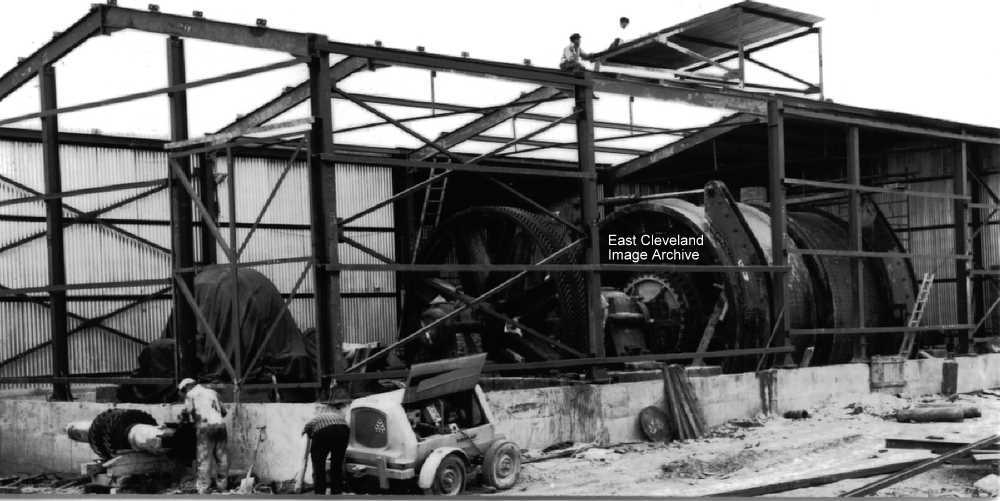
A deep shaft demands powerful haulage gear – and powerful haulage gear demands powerful brakes! – this is one of the winders used for sinking the shafts. These were later dismantled after sinking was complete. Image and description courtesy of Alan Franks.
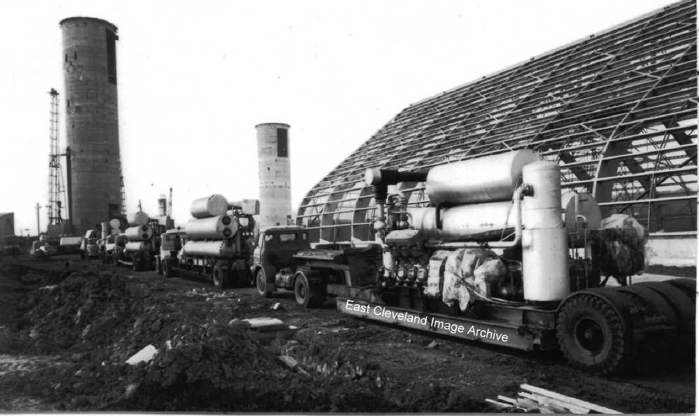
We asked of this image: “Looks like a convoy of big engines – air pumps perhaps?” Aaron Clarke tells us: ”This looks like the freezing equipment which was used in one of the shafts when the ground they were digging down through was too soft to dig through and had to be frozen.” Alan Franks tells us: ”The reason for freezing the ground was because of the amount of water in the Bunter Sandstone at approx 2000 down to 3000 feet down. This was commonly called the ice wall. This was breached while sinking through it, with loads of warm water coming into the shaft. Continuous pumping was done with Pluger pumps enclosed in metal pipes and then 30 feet of gravel and 30 feet of concrete on top. The concrete was later removed by rock breakers ( jiggers ) and hand filled into a cut down Kibble ( big bucket) .While the ice wall was refreezing during this operation the steel lining was installed by a German firm of welders, assisted by us Sinkers. The normal sinking operations recommenced after these operations. This was the Number 1 shaft ( Rock Shaft ), the other shaft Number 2 ( Man Shaft ) was long hole drilled down in stages of about 70 to 80 feet I think there were 32 holes round the shaft floor, then cement and water mix (Grout) was pumped into these holes to seal all cracks in the rock strata to contain the water as in the other shaft. The freezing did the better job of containing the water,also a different steel lining was used ( Tubbings ) these were bolted together and caulked with lead.” Eric Lindsay tells advises: “Indeed the freeze compressors that ran 24/7 with exemption from the 3 day week electricity cuts. The freeze pipes were spiral drilled through the Bunter Sandstone from a chamber formed in the main shaft just above the sandstone. This sandstone was very permeable horizontally but the opposite vertically. The refrigerated brine was pumped down concentric pipes to provide flow and return from the manifolds in the freeze chamber. After the breach in the ice wall was found when they excavated level with it the shaft was plugged as described and the water pumped through valves. The valves were slowly turned off until all shut and the pressure built up below the plug. If I recall correctly the plug moved up that shaft a short distance. Freezing continued until ice wall hole froze over and until the full depth of shaft had been sunk and lined through the sandstone. The steel tubings came from Head Wrightson I think, in matched rings and were shot blasted on site. The segments were bolted together with lead gaskets. One ring was never paid for as they couldn’t supply me with delivery and weighbridge paper work. Image courtesy of Alan Franks, thanks to Aaron Clarke, Alan Franks and Eric Lindsay for the updates.
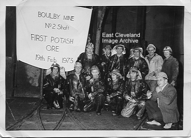
A celebratory group at the bottom of No. 2 Shaft announce the winning of the first potash from the mine on the 19th February 1973. Back row: ??, ??, Bill Casson, Mick Urban, Alan Scott, Willy Brown. Front row: Alan Hall, ??, Tommy Wood, ??, ??, Tommy Hornsby. Image and names to date courtesy of Alan Franks. 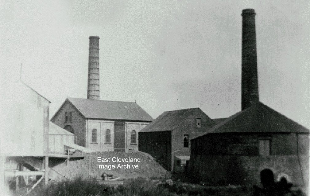 A good image of the engine house at Lingdale mine. The brick-kiln (and associated brick wheel) was part of an attempt to make the mine profitable (especially during slack times). It wasn’t particularly successful, but probably contributed enough to prevent total closure of the mine. Lingdale mine was one of the deeper mines in the Cleveland system and also at the poorest yield, there being a large band of shale splitting the seam in two. This resulted in the huge shale heap which took forever to dispose of! Lingdale village was described as almost derelict in the late Victorian era, the difficulty of winning the stone meaning that the mine was closed more often than in production. Paul Stonehouse tells us: My Granddad worked in quite a few or the East Cleveland Ironstone mines for most of his working life from a young boy to retirement. His name was Douglas Stonehouse and he lived as a young man in Lingdale and then later in Brotton. I know from stories he told me as a young lad that he was an ‘overman’ at one of the mines and I seem to think it was Kiltonthorpe but I can’t be sure. Any information or web sites etc would be greatly appreciated.” Peter Appleton comments: “I am not sure that the statement about Lingdale being the deepest mine is true. Peter Tuffs, in his “Catalogue of Cleveland Ironstone Mines” (pub. April 1999) gives the following depths for shafts: Lingdale 628 feet; North Skelton 740 feet 6 inches. Image courtesy of Maurice Grayson, tany thanks to Paul Stonehouse for that update and query; also to Peter Appleton for the hard facts.
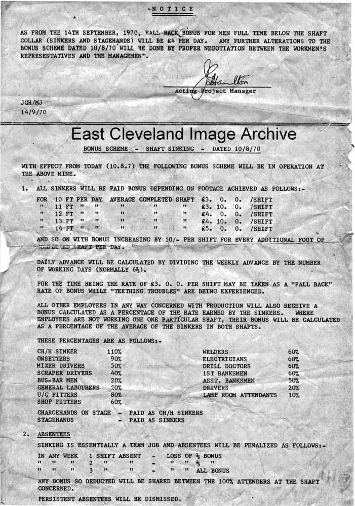
A unique piece of the history of Boulby Potash – the day-to-day dross seldom gets preserved – dating from 1970. Image courtesy of Alan Franks.
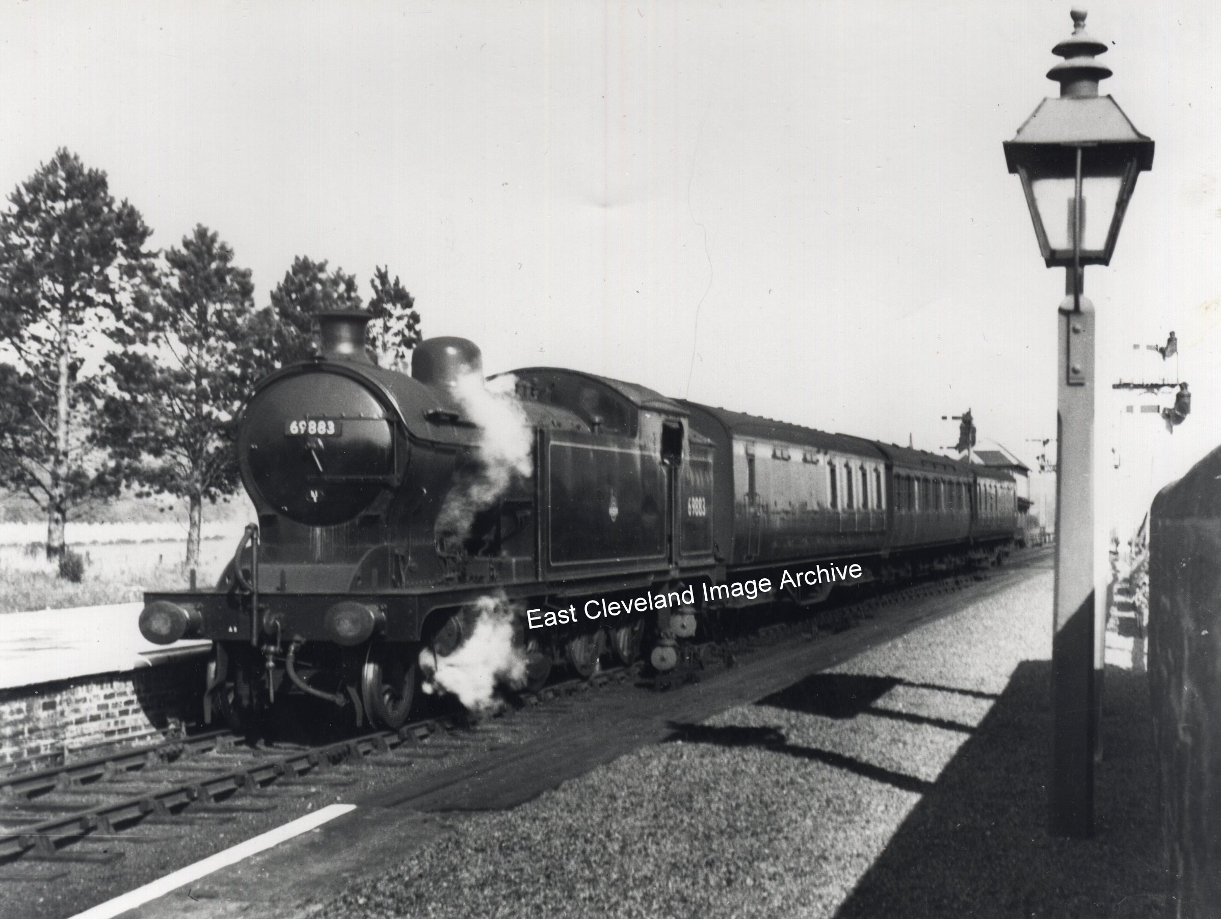
A pristine locomotive – another A8, number 69883 – pictured at Battersby Junction in the 1950’s. Battersby Junction is now a station on the Middlesbrough to Whitby, Esk Valley line; it was originally the junction for the line which connected with the Rosedale ironstone mines. Location identification courtesy of Simon Chapman.
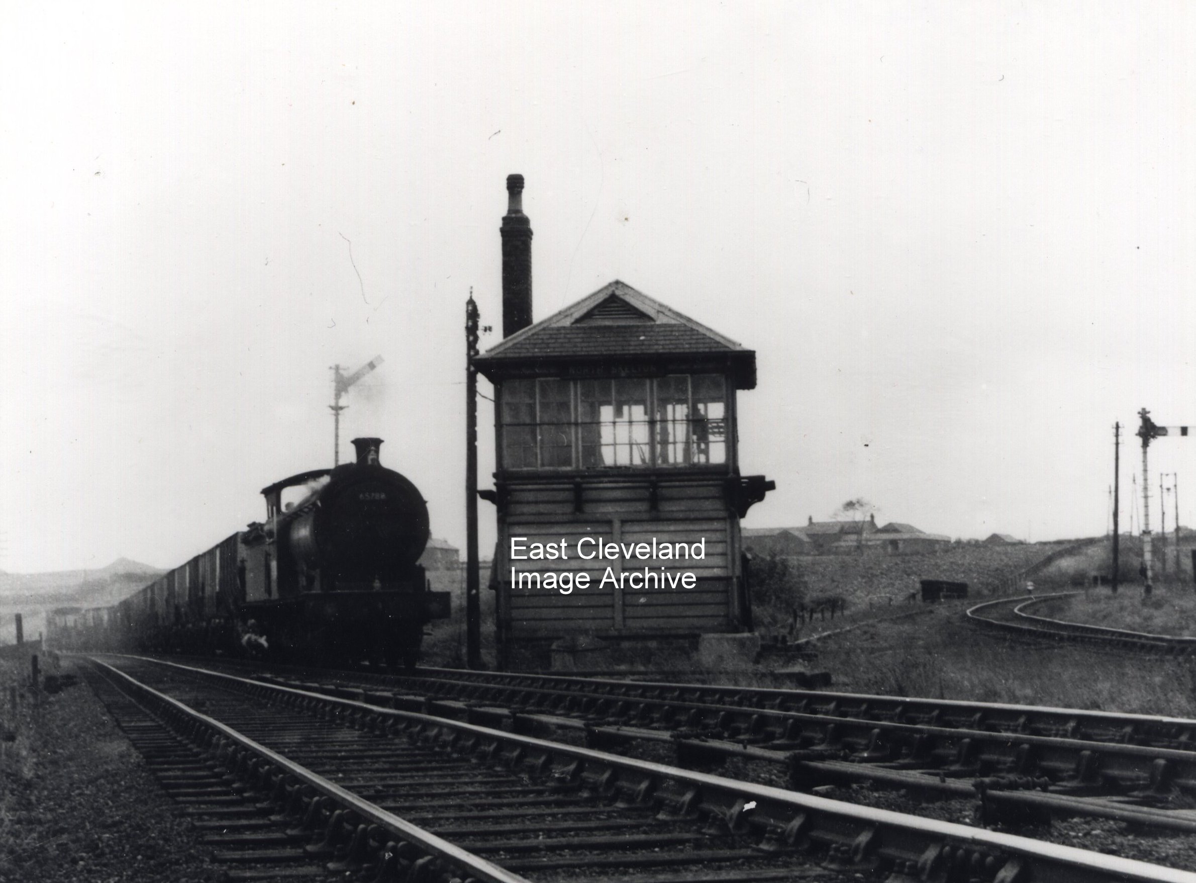
Simon Chapman has advised: “This is quite a well-known picture of North Skelton Junction. The train, hauled by a J27, is coming down the gradient from Brotton towards Saltburn. The line to the right served North Skelton Mine but had originally gone through to Priestcrofts Junction near Boosbeck.” Chris Davies advises:”Engine number would be in the 65780-65894 range as it is of BR Class J27 0-6-0.” Re-posting the image has enabled the Archive to advise that the engine number is 65788. Thanks to Simon Chapman and Chris Davies for this information; also thanks to Ian Pearson for noticing the slip of the fingers in entering the locomotive number. |
||
Recent Comments